Controlling a camera from an external trigger can be very useful. External triggering provides greater timing accuracy, direct control over exposure duration, and remote operation from TTL devices. This is a prime reason I made the Triggerscope controller, so I though it would be useful to explain how this works and what you can do with it.
What is “triggering”?
Most cameras built for scientific imaging or life science have a high density connector located on the back. 90% of the time, this is only used by savvy customers, or OEM integrators (companies buying a camera to place inside a machine for resale). The connector on the back of the camera will typically include 2 basic functions: Inputs (connections which send signals into the camera) and outputs (signals which activate when the camera is in a process or cycle).
Why use Triggering on a camera? Doesn’t the software control image capture?
Of course, software can tell a camera to snap an image. But when will that image be captured? Software needs to do more than say “snap” when you capture an image. Behind the scenes, a LOT of stuff happens!
- the top level controls you see are converted into camera-specific commands via the camera “device driver” in your software.
- The camera commands are fed into a control card or USB port and up to the camera.
- The camera accepts the commands, which activate sets of tables in the camera firmware, to set up a sequence of turning on and off clocks and transistors at very high speed, all depending on your binning, ROI, etc.
- The camera performs the above operations, and sends back an image.
What is quickly apparent is how much has to happen to get an image. In addition, the camera firmware will process some instruction sets faster than others! So some exposures might come back 200ms from issuing the “snap” button, while others will return in 130ms, 30ms, who knows!
So when precise timing is desired, and you really want that camera to fire at a specified time, triggering may be used. In this configuration, all software comms with the camera are pre-compiled, everything’s done. All of the steps above are performed, but the last step, the “camera performs operations above” sits….and waits…for the trigger line to run from 0 Volts to 5 Volts. As soon as that happens, an image is captured. For single frames, this is somewhat useful, but for sequences, this is great. We can capture images at some interval with 100% confidence timing is accurate.
Example
Let’s look at a typical camera, and pull the information we need from the user manual, in order to better understand triggered control. For this post, I’ll use the Photometrics CoolSNAP MYO camera, and as Photometrics makes it easy to read up on the user manual for their products, you can find the user manual here. Page 21 of the PDF describes the various operating modes for the trigger input. Note, the PDF also gives us information on EACH PIN used in conjunction with input and output signaling. There’s more than one!
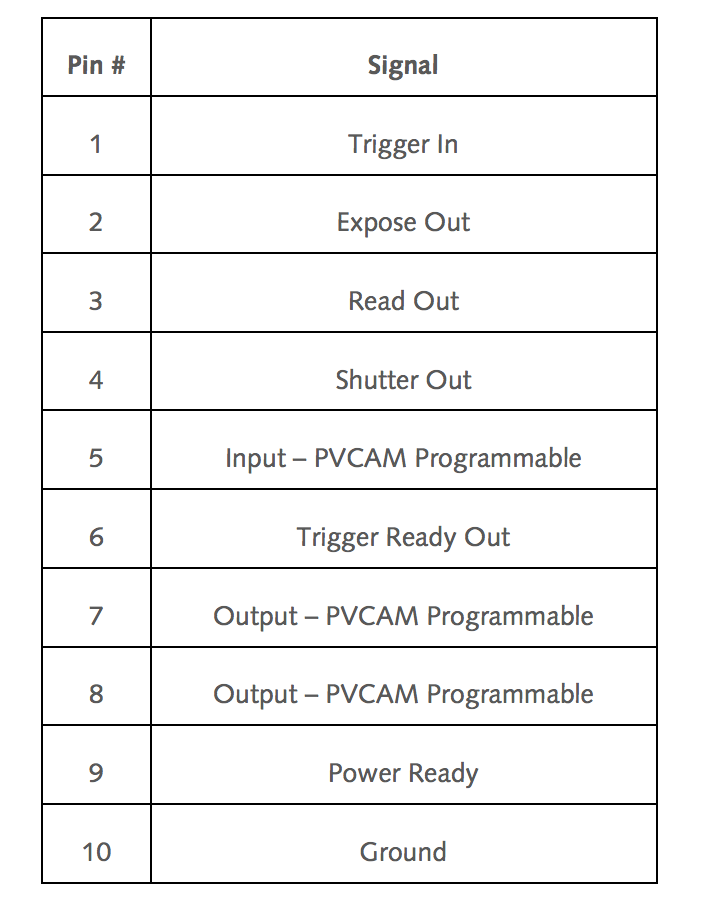
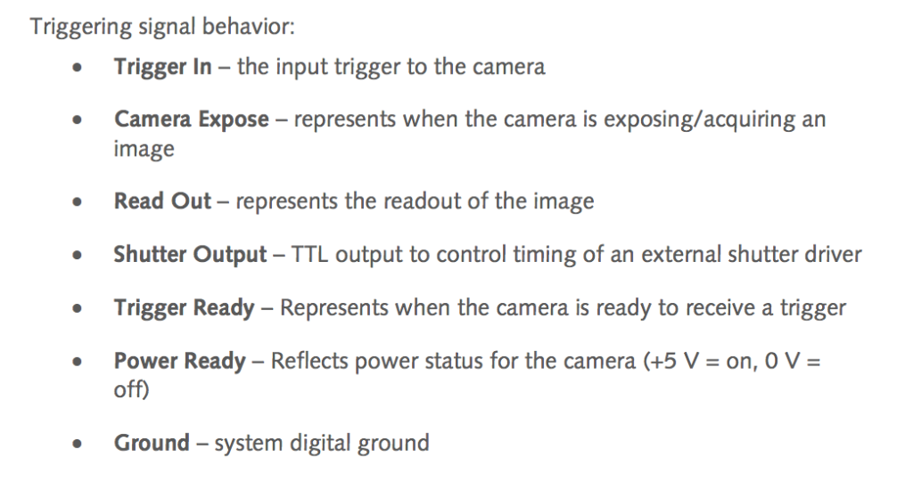
Note, PM also provides short descriptions for each pin:
So – now we know which pins communicate which functions from the camera head connector – to connect to any of these, we’d simply connect a ground wire, and a positive pin wire to our chosen camera pin (for our needs, say Pin 1 – Trigger In)
Now – the most pertinent for us is the trigger in line, which runs in a few modes. Let’s review each, and why we might use them:
Trigger-First (sometimes called other things like “Fire”)
In this mode, the camera is set to snap some # of images (let’s say 10), but waits for a trigger input. Once that input goes high, the camera snaps 10 images as quickly as possible.
Strobe
In this mode, the camera is again configured for some # of images, but every image waits for a trigger.
Bulb
In this mode, the exposure time for each image is controlled by the input trigger. Again, multiple images are assumed (although Image qty of 1 is acceptable), and each frame waits for a trigger input pulse.
These three modes constitute the majority of uses for a typical triggered input line.
So, what does “receive a trigger” actually mean? Good question!
Triggering = TTL Control
Cameras, like almost all computer systems, are made to interact with external systems. One of the oldest, and most common methods, is referred to as “transistor transistor logic” or TTL. This boils down to the concept that if we specify an electrical voltage value of X as “off” and Y as “ON” then we can remotely flip a switch.
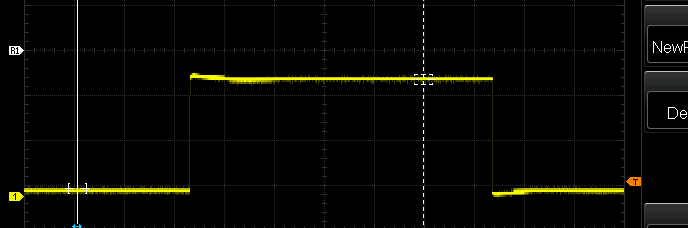
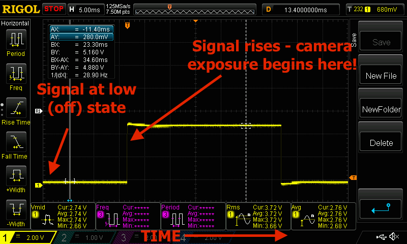
Many imaging devices use this communication method. A simple uniblitz shutter for example, can accept USB/serial data to open and close the shutter, but using TTL is faster and simpler. (just one thing to do, send 5Volts or 0Volts.) Below is an oscilloscope capture of such a signal. The vertical scale = Voltage level, and the horizontal scale from left to right = time elapsed. My annotations are in red. Note the yellow line, which indicates the signal.
Example Signal
Let’s say we have a device, for now, it’ll be the triggerscope 2, which is connected to the “TRIGGER” line of our camera. We want to signal the camera to capture immediately after we turn on an LED. In this case, we might use the triggerscope line 1 for the LED on and off, and line 2 for the camera signal.
In our software, we’d specify the camera exposure time, binning, and other usual parameters. In our controller, we’d set the output to high when we wanted to capture our image. Let’s use an example of 1 image:.
Tell the camera to acquire using software (nothing should happen yet!)
-Camera waits for a trigger signal
Tell our triggerscope to send a TTL high
-Camera captures an image.
Tell our triggerscope to send a TTL low
(nothing changes)
The above sequence can be used for a series of images. In that case, the acquisition would be configured for some # of frames (say 10), and the camera would capture 1 frame each time the signal swung from low to high.
To tie everything together, I’ve recorded quick video explaining this on the scope. Check it out!
[youtube width=”600″ height=”365″ video_id=”4KNe5GxpuOo”]
So – now you know how cameras can be controlled via TTL – if anyone has questions please comment below, so I can address them. Thanks!
-Austin
Comments
One response to “How to use external triggers on scientific and industrial cameras”
[…] Z-stage. You can read more about triggered acquisition on the Micro-manager website and on Austin’s blog. In particular, we’d like to be able to trigger the piezo Z stage of any of the three […]