Required Components and Preparation
For a new Triggerscope 3B shipment, remove from packaging and account for the following:
- 12V power supply
- Mini-USB cable
- SMA-BNC connector cables, if purchased
- ARC certificate of compliance paperwork
- Triggerscope 3B Controller
Hardware Connections
Once unpackaged and all components are accounted for, plug the 12V power supply into the slot located on the left side of the unit labeled “12V,” and plug the other end of the power supply into an available power outlet.
Next, plug the mini-USB cable into the left side of the Triggerscope unit in the slot labeled “USB,” and plug the other end into the computer you are going to be using.
Driver Install
Next, locate the switch on the right side of the Triggerscope 3B, flip the switch either way, both ways turn the Triggerscope on. Open a new tab on your web browser, and download the Arduino IDE Software that matches the Operating System you are currently using. Follow the install prompts to install the software
With install of Arduino IDE complete, open the newly installed Arduino IDE application on your computer.
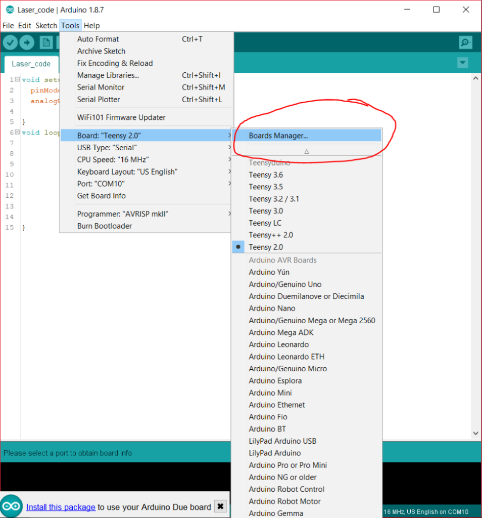
On the top ribbon, select the “Tools” tab. Then hover over the section that says “board” and then click on the “Board Manager” option.
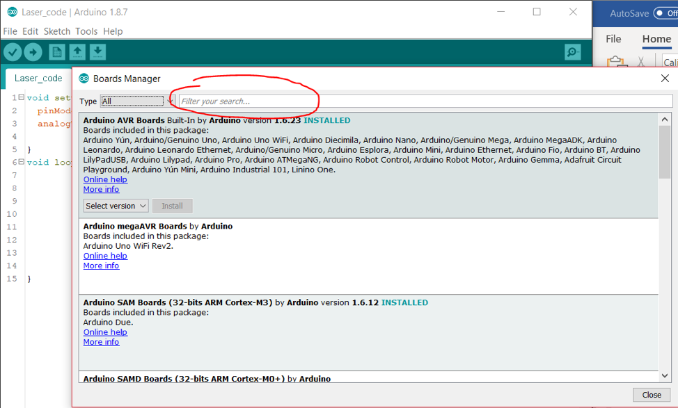
Next, in the “Board Manager” window, click on the “filter your search” box and type “DUE,” and the following should pop up on the screen, “Arduino SAM Boards (32-bits ARM Cortex -M3) by Arduino.” Click install on this option.
The Arduino application will proceed to download and install the driver package needed to run the Triggerscope 3B unit.
MicroManager Setup
Most end-users will already have MicroManager installed, but if not, make sure to use the nightly builds found here.
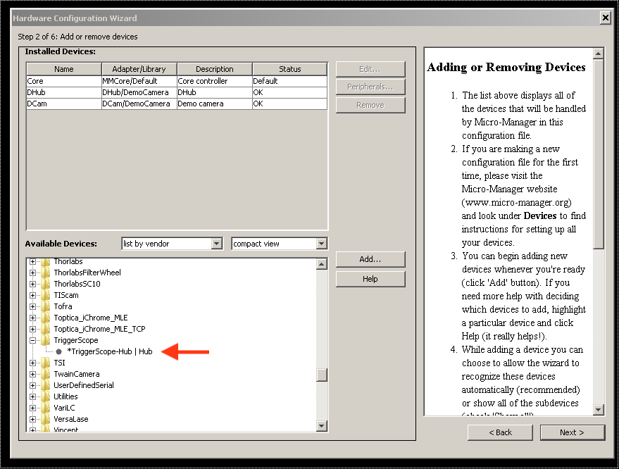
In MicroManager, select the “Hardware Configuration Wizard”, Click Next until reaching step 2. In the lower list, browse to the “Triggerscope” section, and add the Triggerscope Hub Device.
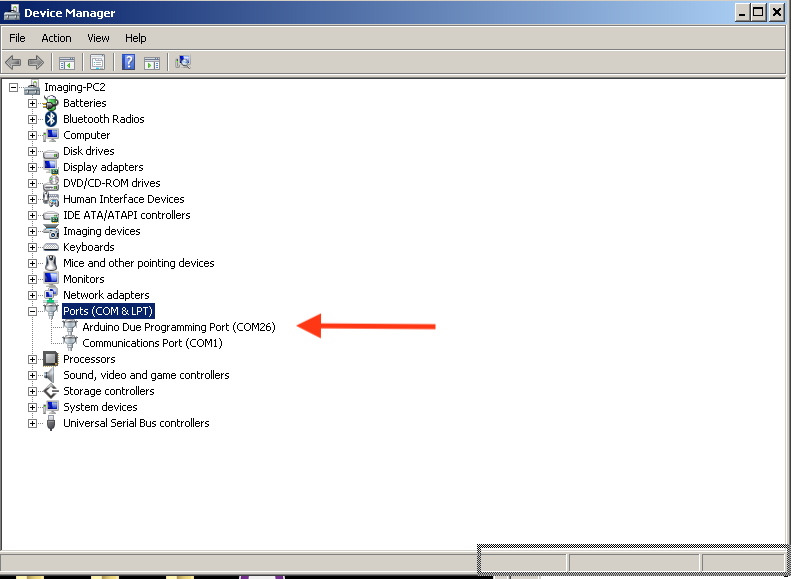
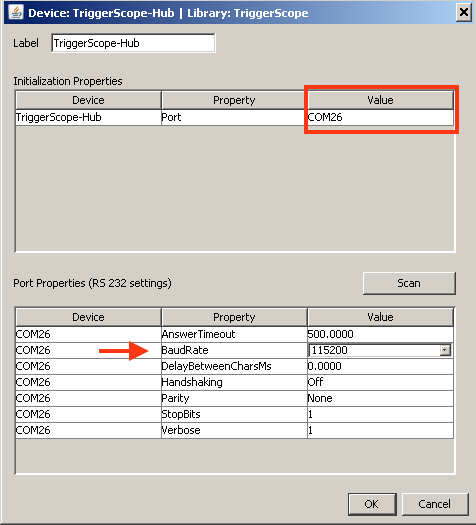
For the Communication setup, select the COM # assigned to your triggerscope under the Windows Device manager, read as “Arduino Due Programming Port”.
Configure the Com # found int he device manager, make sure to set the BAUD rate to 115200.
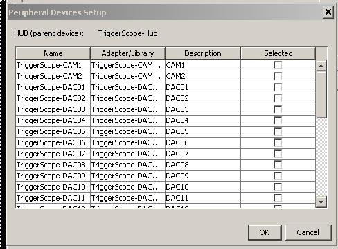
When prompted, select the TTL and DAC lines needed for your application. Also note DAC 16 is tied by default to the FOCUS device. If running sequencing for Z stacks you’ll want to add this.
Continue through the dialog options, if connecting to a Z stage, be sure to specify the maximum and minimum height of your stage so that Z data is properly calibrated. Contact ARC if using a range other than 0-10V.
Next, confirm proper operation by opening up the Device Property Browser. You should have discrete control over the DAC lines added, and on/off state control over TTL lines. Note that the Triggerscope 3B will illuminate an output LED when DAC control is enabled, or when TTL control is enabled. This can be very useful to confirm proper communication with the computer.
This concludes the basic setup for Triggerscope 3B. Please contact ARC with any questions if you are having difficulty!