Many people who own a Nikon C2 or A1 confocal may not realize it, but the laser launch used with these confocals may include an optional second fiber output. The LU4-A version of Nikon’s laser launch includes a 2 fiber option for systems which may use TIRF and confocal. Some TIRF standalone systems are also sold using the LU4A, for later upgrade to a confocal.
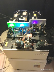
So let’s say you have a TIRF system, but instead of using a point scanning confocal like the C2 or A1, you instead opt for a spinning disk system? Things get interesting: For some reason that defies all logic, Nikon’s LU4A launch has two fiber ports, but only one fiber output is accessible via NIS elements! When using the second port, the launch expects control from a Nikon confocal (A1 or C2) and therefore locks out elements from driving the lasers on that second port. For many customers who want to run a spinning disk, or use the second port for FRAP, this is a major limitation to the launch’s usefulness.
So, I had a chance to work on one and come up with a bypass to this restriction.
Basically the LU4A uses a 12 volt DC motor which controls port selection. There is a mirror system used that only requires the motor to turn an optic assembly 90 degrees in one direction or another, to provide light to a fiber.
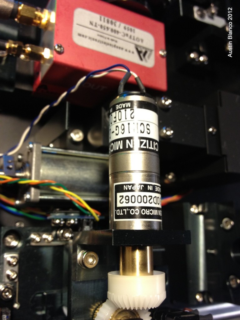
On each position for output there is an IR interrupter sensor, which stops the motor movement in the correct location. There’s also a physical pressure type switch on one port
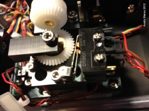
So, basically all that needs to happen in order to bypass the port restriction is to take over control of the DC motor and it’s two sensors. Luckily there’s an inexpensive way to do this. A robotics company called Pololu makes a nice $35 USD DC motor control board.
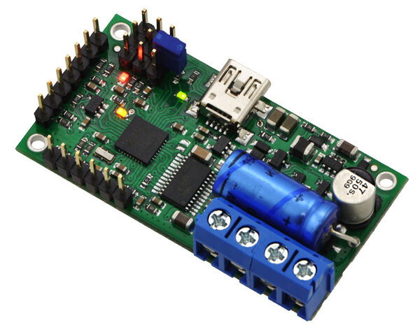
The board includes the options for 2 limit switches, and even has internal pull-up resistors to supply some differential current to the sensor. I can imagine using the board for all sorts of applications. It has control inputs for TTL, variable voltage, joysticks, a USB direct driver and RS-232 ASCII control over the USB line. The board ships with very easy to use control/setup software, making development painless. This level of access makes the board extremely easy to program and also very easy to control from inside NIS Elements. The setup and programming of this board took about 1 hour in total!
Armed with my control board and a few switches I hacked the launch. I found several interesting things:
First, there is a single unified connection point for all fiber control cables. Second, if this is disconnected, it seems the LU4A firmware just decides that it is a single fiber system, and ignores fiber control inputs from the remote control box and from software.
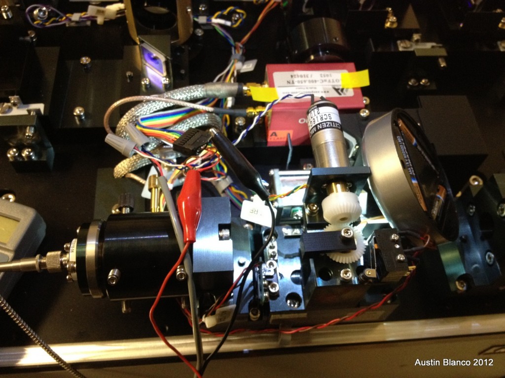
Third, because these are disconnected, you lose the power input for the interrupters, meaning you’ll need to either power these yourself, or provide a switch of some type for one of the two positions. I opted to use a reed sensor on one side, and to position this sensor at a point just near the physical stop of the optical assembly. It was surprisingly easy to set the sensor up in a position which provided full power into the fiber. Initially I was concerned with alignment changes via the sensor, but the reed sensor hits at about the same time as the physical stop, so this provides reliable positioning, where the sensor cuts motor control before torquing against the stop too much.
So ultimately, all that is needed is to disconnect the multipin connector, cut the two wires for motor control, cut the two wires for the pressure switch, and add in your extra sensor for the second port position. (Or optionally you could cut into and access the photo interrupter switches, as these are already positioned for use.)
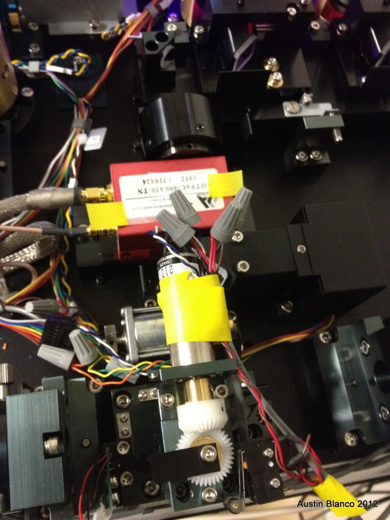
The motor used in this application is quite interesting. It’s a “Citizen Micro” SCR-2504. What’s interesting is the planetary reduction gearbox mounted to the front of the motor. This gearbox allows for a large reduction in step distance from the output shaft, so if you move this motor in small amounts, you see extremely small changes in position of the fiber selection setup. This means you can get very precise control of the system position. I found that a control speeds under 40% on the Pololu, it was hard to even view the change in position of the optical selection assembly for the fiber. When setting up the Pololu board I enabled an acceleration/deceleration curve, (decent slope) to reduce overall torque when starting and stopping the motor. I also set a maximum speed well below what the motor can handle. This switcher is not intended for high speed applications, so by slowing down the system a bit I gave myself a little more margin for error on the stop point setup of the reed switch, and also reduced system wear a bit.
So – once you know what the parts are inside this system, controlling them is actually not too tough. Remember that once done you’ll need to make a driver for Elements. Mine was simple, with a “move forward” serial command to go to position 1 (which the controller will do until the forward limit switch is tripped) and a “move back” command for opposite control to the second fiber port. I believe the total serial control string was “F3200” for forward and “R3200” for reverse, with 3200 being the A/D speed setting. Very simple to set up in Elements using the serial “Writeport()” function. Just make sure to thoroughly test the finished setup before locking down your new wires (away from the beam path!) and replacing the cover!
-Austin