This page is a resource for the Students of John Adams Academy who are attending my course on embedded electronics.
Week 7 – No Door! We move to Alarms 🙂
I’ve been informed that the automation of the door will exceed the allowable damage threshold the school has on it’s equipment. (I.e. we WILL be drilling hoels all over it and the wall, which means someone would have to undo all of that later on).
So – we have 28 students, 25 Arduino’s, and 3 weeks remaining to complete a project. What shall we do? I think we should continue with almost every aspect of the door, without the motion of the door itself – i.e. let’s build alarms!
Today’s work will consist of the following:
- review test questions
- form project groups
- Define program/system requirements
- begin program layout for specific alarm project
- Determine if any additional hardware is needed*
Week 6 – Mid Term Test & Project Measurements
For the beginning of our class, I’d like to find out just what information has sunk in.
Week 5 – Sensors!
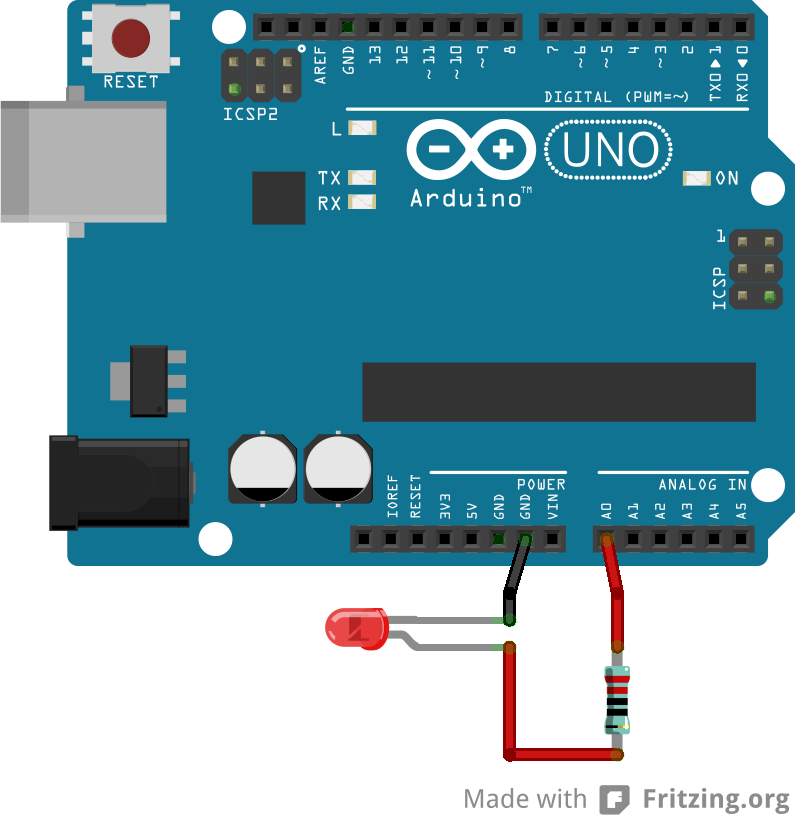
We’ve seen how the controller can drive a device such as an LED, but what about measuring inputs? Well, it turns out we can measure the bias of an LED, and use this as a way to measure ambient light!
The same principle which drives the LED can work in reverse. So in this case, the greater the photons in the environment which hit the LED phosphor, the greater the boas, then the greater the analog measurement we will see on the connected LED input pin.
In order to accomplish this, we’ll need to connect the LED to an ANALOG input pin, let’s use A6. Next, we’ll connect the standard ground side to any GND pin. Note on your setup, we have the resistor connected directly to the LED pin, so there are no red or black wires needed.
Next, we’ll need some code
For this code we want to measure the A0 input. In order to do this, we will need to store this measurement in a variable, so we’ll create an int type variable. For instance
int myValue;
myvalue = analogRead(A0) ;
The code above would create a variable, called “myValue” and then would record whatever the current reading is measured from A0 into the myValue variable. We can then use this variable for later work.
In our case, we will use this # to drive the on-board LED which is provided with our Arduino board.
To do this, we’ll need to drop the resolution of the original measured value. In this case, the input value is 10 bit (remember 2 power of 10 = 1024) to an 8 bit value (x4 or x2 to keep the gain high).
So – we can take myvalue = myValue / 2. This will drop the original value to 1/2 it’s measured #.
Next, we assign that value to the built-in LED, using the analogWrite function we used last week.
analogWrite(13, myValue);
This series of steps can be found in the following example code.
Week 4 – We get to drive some Devices! LEDs, Motor Control, Voltage and PWM.
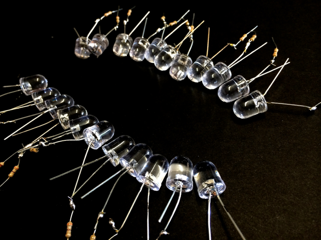
Now that we have a basic understanding of writing and accessing variables, we can move into the world of robotics! I’ve spent some extra time and cooked up a LED for each student in the class.
In order to drive devices, we must supply electrical charge to the device(s). There are a number of ways to do this, but all electrical signal boils down to some simple laws.
First, is Watts. Watts are a universal measurement of electrical power, and can be calculated by Watts = Volts * Amps. Consider for our work a simplified explanation: Volts is a measurement of the number of lanes in a freeway.
Amps is a measurement of how many cars are on a freeway.
Therefore, Watts = # of Lanes in a freeway * # of cars per lane.
Our LED is rated at about 0.3 Watts of maximum power.
Our Arduino can drive, on a single pin, about 40 Milliamps (0.040Amps) @ 5Volts, or 5*0.040 = 0.2Watts, in other words, our LED’s and our Arduino power lines are well matched!
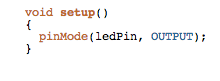
Now, to turn the LED on or off, we must begin some Pin declarations. These are functions built into the Arduino language, (found here) First, we need to tell the compiler language that we want to use a pin as an output (rather than an input, they can both read in or send out- cool huh! )
So, the command to set the pin is: pinMode(The Pin #, OUTPUT);
Where the pin # = whatever pin you want to use.
Once we have this, we will use digitalWrite(Pin #, High or Low); to control the pin. For instance,
digitalWrite(7,HIGH); will set pin 7 to ON.
Don’t take my word for it! I’ve provided some simple code for you to try:
Now this is great! We should have an LED on Digital pin # 6 flashing off and on. But what else can we do?
This brings us to the use of PWM, or Pulse Width Modulation. Imagine if we could control our freeways, not by reducing the # of cars globally (i.e. lowering current – this BTW is referred to as a “constant current” power supply), but in a simple way. We already do this on California freeways. Notice the flashing freeway onramp lights when you enter a busy freeway? These lights are only green or red, and they allow one car or two cars per time value, so that say 2 cars per minute = 120 cars per hour. We will do the same with PWM. PWM controls, at high speed, the on/off state of the pin referenced. Now some pins can be controlled by PWM and some cannot, luckily pin 6 can, so, by controlling PWM, we can control the frequency of the power being delivered, and thereby control the brightness of our LED, by chopping down the power per time.
Here’s an example from, where else” The Arduino website!
To do this we will use the analogWrite command, where:
analogWrite(pin #, analog value 0-255); for example, if we wanted to drive pin 6 at half power from full on, we would send the 1/2 value in an 8 bit range. Now 8 bits ave a range from 0-255, so 1/2 of 255 = 128. So we would write analogWrite(6,128);
For a better example, check out this code, it uses a FOR loop (remember those? It’s only been two weeks!) to drive the PWM output up 1 time per 10 milliseconds, and then repeats a loop in the inverse to drive the brightness down.
Now – once you have the above examples working, try playing around with loops, variables, and figure out some cool stuff to do with your LED!
Week 3 – Loops & Arguments
Last week we discussed some fundamentals of the programming language, now let’s look at how to leverage the language to make our programmable brain “think” on it’s own.
Argument – Makes the CPU decide “Yes” or “No” to a condition.
- IF (a condition is met) THEN (do something)
- IF (condition 1 is met && condition 2 is met)
- IF(Condition 1 is met OR condition 2 is met)
Loop – Makes the CPU keep doing something as long as the loop condition is met
- While loop – Says, “Keep doing this while a condition is true”
- For While loop – Says “Keep doing something, and each time you do it, change the value of this variable”
Examples
- While (a button is NOT pressed) {keep a door lock closed}
- For (counter = 1; while counter is < a measured distance; add 1 to counter for each loop ) { Step a motor to move a robot to the measured distance }
Example Code – Find the example Code HERE
Week 2 – Programming Fundamentals
Last week we were able to program our controller, and watch it respond to our input commends. Cool stuff! But how did our commands make the microcontroller respond in the way it did? Of equal importance is the larger question, how can we properly write to this controller?
So begins our journey into the world of C programming. Let’s review from last week the basics:
A common code example:
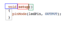
Blue = VOID – This is the value which will be returned by the subroutine – i.e. if the subroutine is to perform a job, it may return a result flag (0=failed, 1=success) or it may return a calculated result.
Red = SETUP – Names the function for access by your code and by system
Green = ( ) – Input variables, numbers which the subroutine can accept and use later.
GRAY = { } – Code Block, defines the beginning and ending of your code.
Stuff between bars = code you want to run.
Some examples:
This code works: void runme(){ delay(100); }
This code fails: void runme({delay(100);}
why?
Variables
A variable is simple a place to put a number, series of numbers, or text.
int = a whole number, ranging from -32768 to 32767
float = a fractional number, ranging from -3.4028235E+38 to 3.4028235E+38
char = a single ascii character, which is saved as a number, but can be accessed both ways.
string = a series of characters, i.e. “text” can be a string.
Calling functions and subroutines
Let’s say we’ve made a subroutine, or we want to use one of the many subroutines already built into the arduino environment. In this case we access the function or subroutine by calling it inside a code block. Last week we worked on delay. let’s explore this:
int loop() {
delay(100);
}
Note the 3 parts of the delay call:
– The name of the function or subroutine
– The open and close parenthesis, which are filled with a number in this case.
– the semicolon, which finishes or closes the command – consider this like a period at the end of a sentence
An example of a function called to write to an LED array:
strip.setPixelColor(20,255,0,0);
where the function tells an LED array to turn a pixel on, the first # sets the pixel address, and the other 3 numbers provide red, green and blue brightness levels.
So functions can be very simple, or very complex!
Simple timer Example
//***BEGIN CODE
long stopTime; //creates a holding variable
void setup(){
Serial.begin(9600);
Serial.println(“Timer Example”);
stopTime = millis() + 3000; // This takes the current internal clock, + 3000ms, and places the result in our stopTime variable
}
void loop(){
long countDown = stopTime – millis();
delay(200);
Serial.print(“timer = “);
Serial.println(countDown);
}
//***END CODE
Run the code, now let’s improve:
-What happens when the timer runs out?
-How can we address this?
Week 1 – Intro to the microcontroller – a programmable circuit!
Code for this session can be found here.
- We are using the Arduino Uno (Which has the ATMega 328 Microcontroller at it’s heart)
- The Arduino board is an easy-access breakout system to communicate with the ATMega
- The board provides several components needed for operation.
- The Arduino at minimum Requires
- Power (7-12 Volts DC)
- Communication for programming it (USB Cable connected to a computer)
- Method of writing / uploading code (Development Environment or IDE Found Here)
- Your code!
- Code Structure must contain at minimum
- A Setup block
- A Loop block
- Overview of Arduino Uno Pins

Comments
8 responses to “JAA Course”
Hell Mr. Blanco,
This is Clayton Dahlstrom from your jaa class. i cant start up my arduino on my pc!!! The laptop is ACER. I just cant find where the application is. it is plugged in and ready but i cant find it. Please email me soon.
– Clayton D.
Hi Clayton, Please use the software from this link – download whatever is appropriate for your computer (likely the windows EXE) and install, then it should work.
To get this running you’ll need:
1. the program installed
2. The board DRIVER installed (check this under COM POrts ni the windows “device manager”
3. once above is done you can select the correct COM port for your connection. Note that if you connect to different USB ports the com # may jump values. (i.e. change from # 4 to # 7 or so forth).
Hello, Mr. Blanco, I have finished installing my arduino and I have a string of code correctly imputed into the program but whenever I open up the serial monitor it always shows up blank. I have windows 8 and here is the code:void setup()
{
Serial.println(“Hello world”);
delay(9000);
}
void loop()
{
Serial.println(“Hi….”);
delay(5000);
}
Hi Constantine,
You only need to add a “serial begin” command before everything else. Just inside the void setup.
so like:
void setup(){
Serial.begin(9600);
Serial.println(Hello World”):
etc…..
The serial begin command activates the serial port, and the 9600 specifies the baud rate (or speed). Just make sure your serial monitor window also is set to 9600 in the lower right corner, which it should be by default.
Hi Mr.Blanco, I was wondering how to access the windows hp equivalent of the serial monitor. also I’m trying to figure out how I can use this code that I found on the Arduino website; its a screen saver and I’m trying to figure out how to implement it and what to implement it into. the code is as fallows;
/*
Dragonkeepers:
16×2
FootPrints ScreenSaver / Loading Screen
*/
#include
LiquidCrystal lcd(7, 8, 9, 10, 11, 12);
byte footp1[8] = {
0b00000,
0b00000,
0b00111,
0b01000,
0b10000,
0b10000,
0b01000,
0b00111
};
byte footp2[8] = {
0b00000,
0b00001,
0b11110,
0b10000,
0b10000,
0b10000,
0b10000,
0b11111
};
byte footp3[8] = {
0b11110,
0b00000,
0b00000,
0b00000,
0b00000,
0b00001,
0b00010,
0b11000
};
byte footp4[8] = {
0b00000,
0b10000,
0b01000,
0b01000,
0b10000,
0b00000,
0b00000,
0b00000
};
byte footrv1[8] = {
0b00111,
0b01000,
0b10000,
0b10000,
0b01000,
0b00111,
0b00000,
0b00000
};
byte footrv2[8] = {
0b11111,
0b10000,
0b10000,
0b10000,
0b10000,
0b11110,
0b00001,
0b00000,
};
byte footrv3[8] = {
0b11000,
0b00010,
0b00001,
0b00000,
0b00000,
0b00000,
0b00000,
0b11110
};
byte footrv4[8] = {
0b00000,
0b00000,
0b00000,
0b10000,
0b01000,
0b01000,
0b10000,
0b00000
};
void setup() {
lcd.createChar(1, footp1);
lcd.createChar(2, footp2);
lcd.createChar(3, footp3);
lcd.createChar(4, footp4);
lcd.createChar(5, footrv1);
lcd.createChar(6, footrv2);
lcd.createChar(7, footrv3);
lcd.createChar(8, footrv4);
lcd.begin(16, 2);
}
void loop() {
int sensorReading = analogRead(A0);
int delayTime = 1000; /*map(sensorReading, 0, 1023, 200, 1000);*/
lcd.setCursor(0, 0);
lcd.write(5);
lcd.write(6);
lcd.write(7);
lcd.write(8);
delay(delayTime);
lcd.setCursor(3, 1);
lcd.write(1);
lcd.write(2);
lcd.write(3);
lcd.write(4);
delay(delayTime);
lcd.setCursor(6, 0);
lcd.write(5);
lcd.write(6);
lcd.write(7);
lcd.write(8);
delay(delayTime);
lcd.setCursor(9, 1);
lcd.write(1);
lcd.write(2);
lcd.write(3);
lcd.write(4);
delay(delayTime);
lcd.setCursor(12, 0);
lcd.write(5);
lcd.write(6);
lcd.write(7);
lcd.write(8);
delay(delayTime);
lcd.setCursor(15, 1);
lcd.write(1);
delay(delayTime);
lcd.clear();
lcd.setCursor(0, 1);
lcd.write(2);
lcd.write(3);
lcd.write(4);
delay(delayTime);
lcd.setCursor(3, 0);
lcd.write(5);
lcd.write(6);
lcd.write(7);
lcd.write(8);
delay(delayTime);
lcd.setCursor(6, 1);
lcd.write(1);
lcd.write(2);
lcd.write(3);
lcd.write(4);
delay(delayTime);
lcd.write(6);
lcd.write(7);
lcd.write(8);
delay(delayTime);
lcd.setCursor(12, 1);
lcd.write(1);
lcd.write(2);
lcd.write(3);
lcd.write(4);
delay(delayTime);
lcd.clear();
}
this is most likely not raw code. but I just copied and pasted from the
Arduino program.
Hi Jensen – you’ll need the LCD screen this code references in order for this to work – but good find!
Regarding serial monitor please google “arduino download” and download the windows Xp version. Then make sure to install the serial driver and you should be all set
Dear Auston,
At home, I’m having a problem, a code I’m using to make a clock & a calendar, when I put in the time command it says that there are too many arguments for it to work. What does that mean?
-Scott S.
Hi Scott,
If there are too many arguments then likely there is a line in the code which uses a reference, or other command, that has too many #’s inside it.
For instance, if we used a CORRECT delay function we could call delay(300). But if we put delay(300,200) this would return the “too many arguments” error. can you copy+paste the code which is causing the error?