So I needed to set up an Arduino Mega as a signal processor. I had a sawtooth signal coming from a device, and I wanted to convert that signal to a 0/5V TTL signal. Now, with something like a sine or sawtooth wave, the question becomes, “At what point do I want to consider this signal to be “ON”?” This is where a comparator comes in. Basically, a comparator references a different voltage you supply, and compares your supplied voltage to the measured voltage. There’s a detailed example of how this works using an Arduino in this instructable.
Now, that ‘ible is nice, but note it’s written using an UNO, and unbelievably, the Mega 2560, a more capable board, DOESN”T have the AIN0 pin connected to a breakout line!!!
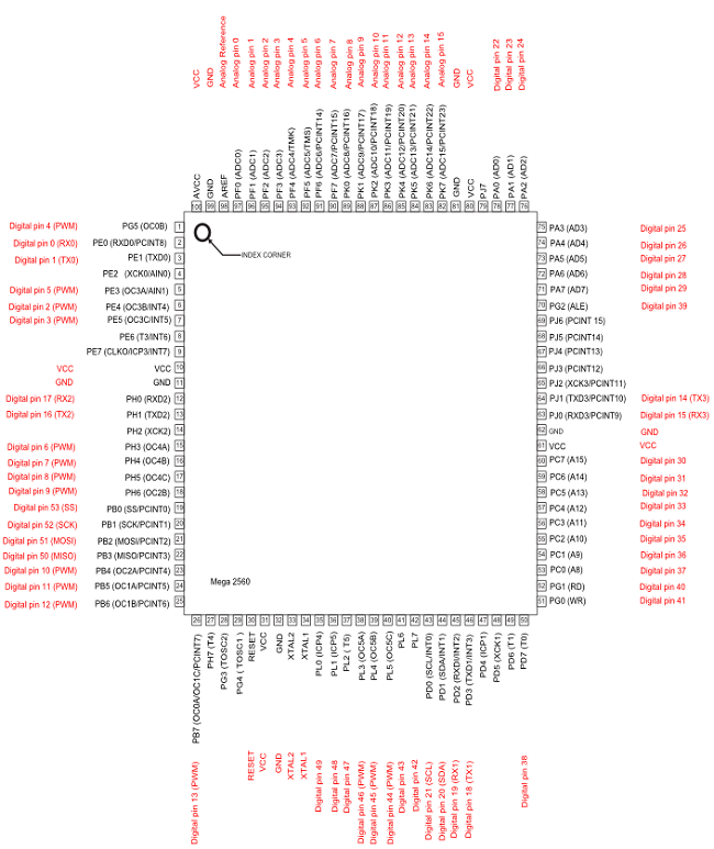
Looking closely at this pinout, we’ll see that indeed, AIN1 is mapped to D5, but AIN0 is just out there with no love!!

So what to do?
Well, I considered just soldering a tap directly to the pin, but I was afraid of thermal issued in doing this, and it’s a small pitch, so instead I looked around a bit more at the functions used for the cmparator (ACSR Command) in the Atmel docs. It turns out, there’s an on board reference (1.1V) which can be used w/ AIN0. This is called using the ACSR command, and I went ahead and used that, as for my needs it worked great. BUT, Your mileage may vary.
Here’s an example of the code I used:
void setup()
{
pinMode(5,INPUT);
pinMode(40,OUTPUT);
digitalWrite(40,HIGH);
//Serial.begin(9600);
ACSR = B01011000; // comparator interrupt enabled and tripped on falling edge.
}

/*ACSR =
(0<<ACD) | // Analog Comparator: Enabled
(0<<ACBG) | // Analog Comparator Bandgap Select: AIN0 is applied to the positive input
(0<<ACO) | // Analog Comparator Output: Off
(1<<ACI) | // Analog Comparator Interrupt Flag: Clear Pending Interrupt
(1<<ACIE) | // Analog Comparator Interrupt: Enabled
(0<<ACIC) | // Analog Comparator Input Capture: Disabled
(1<<ACIS1) | (1<ACIS0); // Analog Comparator Interrupt Mode: Comparator Interrupt on Rising Output Edge
*/

volatile boolean sOn=false;
unsigned long timer;

void loop()
{
if(sOn)
{
digitalWrite(40,!digitalRead(40));
sOn=false;
delay(10);
}

}

ISR(ANALOG_COMP_vect)
{
sOn=true;
}
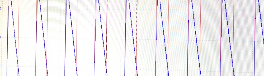
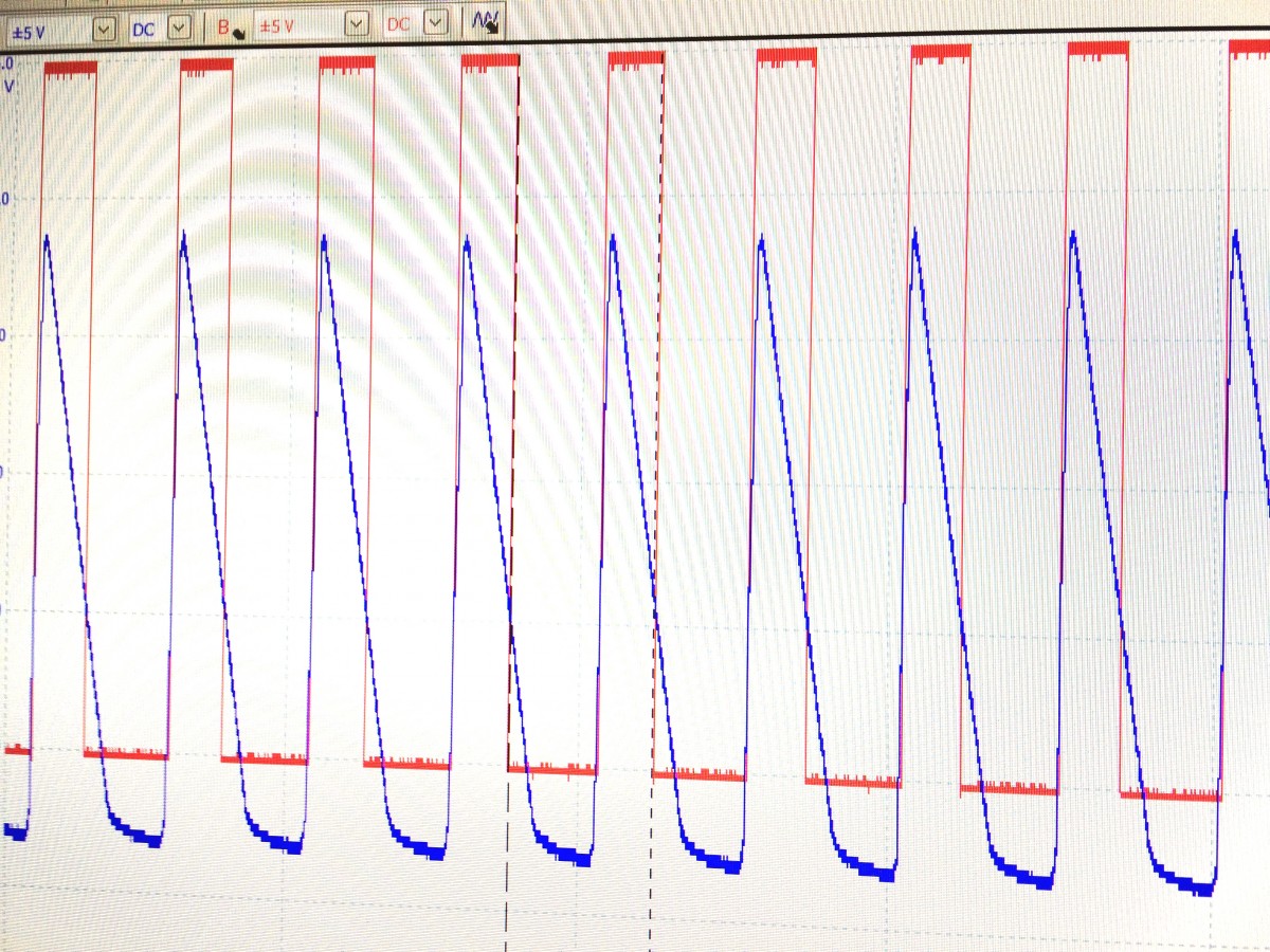
Here’s the output generated from this code against my source wave, the red channel shows the behavior of my output pin. I’m happy with the result, and it’s fun to learn (another) cool thing that the Arduino can do!
 -Austin
Comments
3 responses to “Arduino Mega 2560 Comparator”
Thanks for posting this, and the code. Most of the postings I have seen on this topic _neglect_ to mention that AIN0 is available on a pin on the UNO. So this is helpful, especially as it shows how to use the internal 1.1V reference. I need to use the comparator on the Mega, so am going to try it out right now. Thanks again.
your code is using input,7 which is the nano pin, the mega pin is 5 (AIN1) as shown in your drawing…you should comment that in your source….thanks
Thanks for catching this!