Imaging, Microscopy and More
-
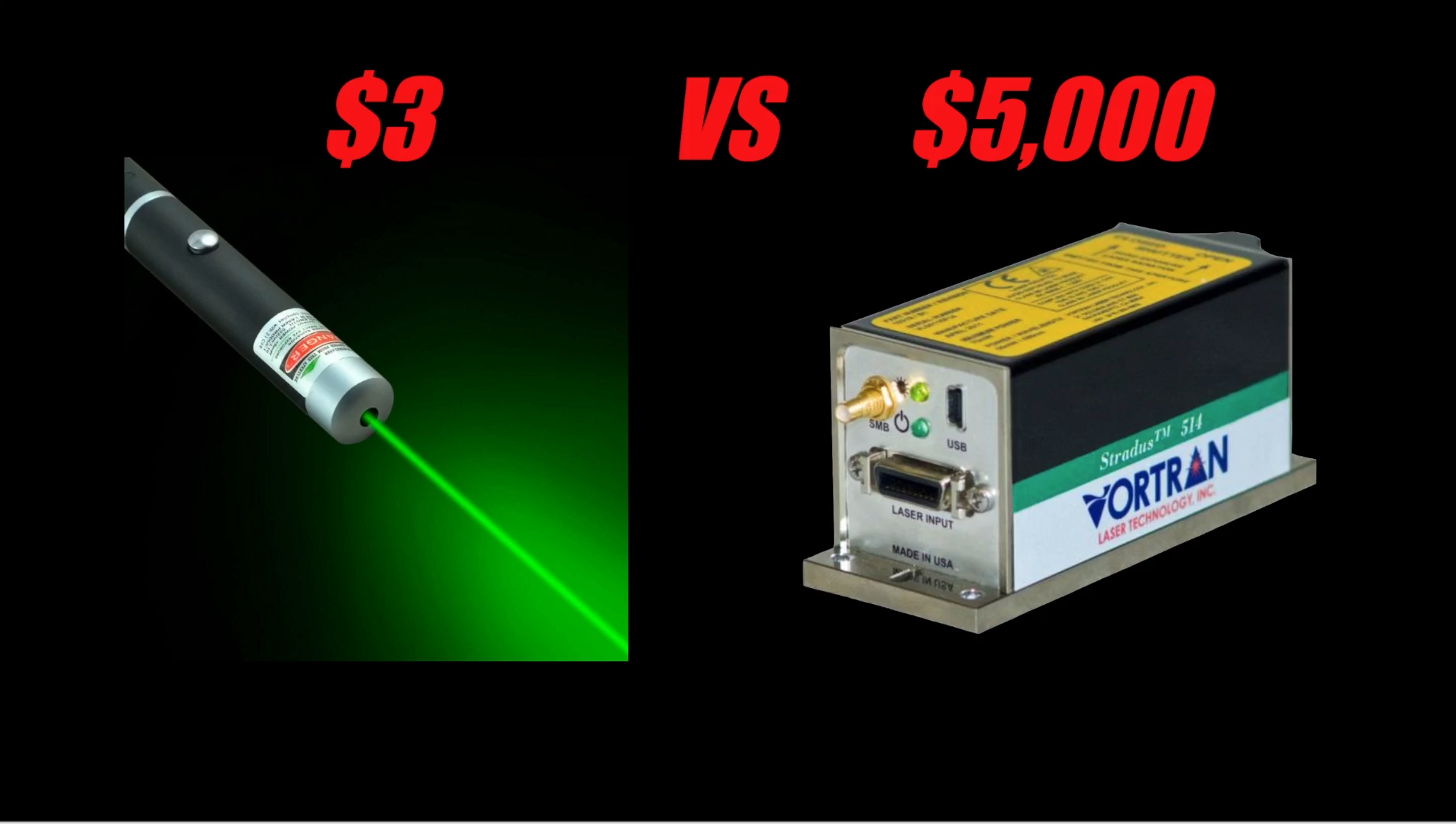
Why a $3 laser vs $5000?
I made a short video describing why laser pricing is so different. Much of it comes down to how precise the beam performance needs to be, and as with so many similar fields, as precision becomes better and better, pricing begins to log scale up as the challenges increase. Thanks for watching!
-
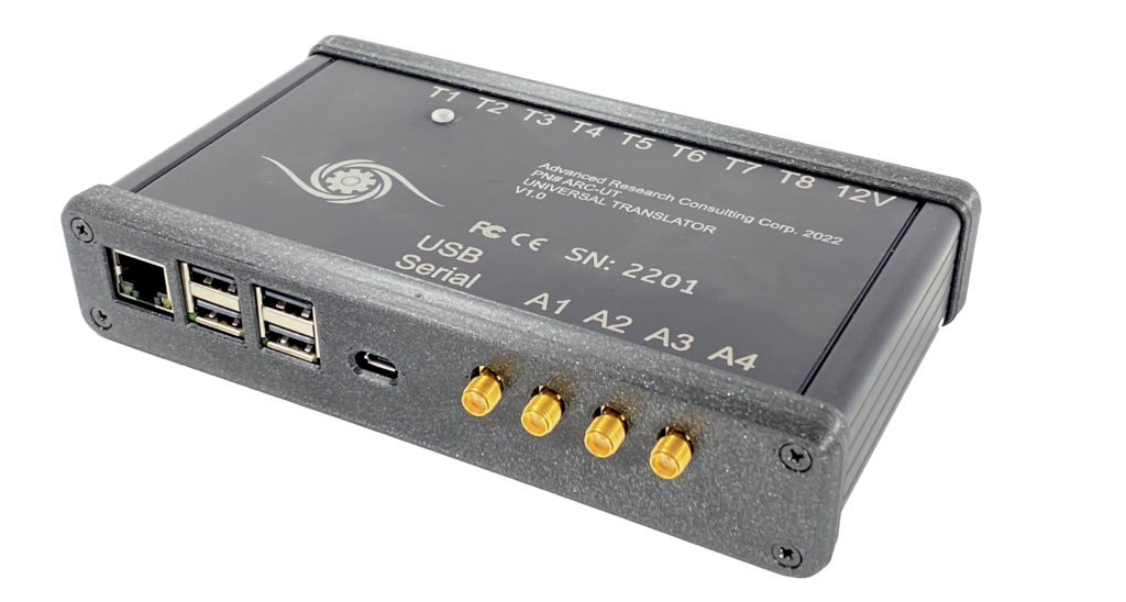
Introducing the ARC Universal Translator
There is a constant problem in the microscopy community, which I have stumbled upon too many times to mention, over the last 20 years. An end user purchases a microscope, with “imaging software” included in the purchase. At some time in the future, the user decides to add a new device, or capability, to the […]
-

Firmware setup for Micromanager
Here is a quick video on how to get going with the TriggerscopeMM Firmware and Micromanager 2.0 Gamma. -Austin
-
Triggerscope Driver Available for Volocity
ARC now has a driver available for users of Quorum Volocity microscopy software. New releases of Volocity will include native support. If you need a driver file or assistance please contact ARC for support. -Austin
-
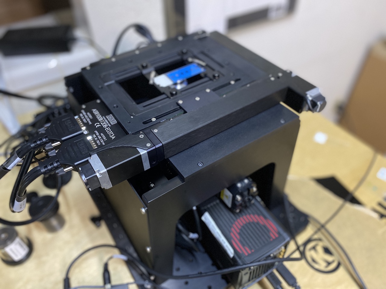
Zaber MVR Automated Invert Review
By: Austin Blanco & Garrett Bunch One of the toughest aspects of working as a consultant engineer is that the coolest and most interesting projects are the ones I don’t get to talk about or share online! But as time marches on, sometimes I get to share a few of my secrets. One of those […]
-
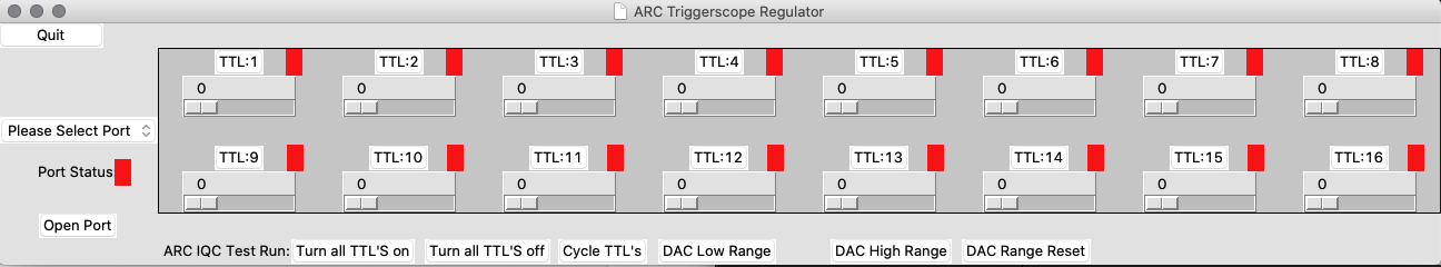
Setting Triggerscope Range Values
Here is a quick example of using the RANGE controls in the Triggerscope GUI Application, as well as an example of saving ranges to the on board SD Card. EDIT – Fixed Video link!
-
Triggerscope 4 Getting Started Video & MM Firmware
We’ve made a new video example of how to get things set up on the Triggerscope with the “Micromanager” version firmware from Nico. Please take a look if you are interested in updating your Triggerscope to use this code, or if you want to learn more about using Shutters, blanking, and presets for the -MM […]
-
New Product Announcement – 3.3 – 5V TTL Level Shifter
Recently one of my clients was working with a Blackfly S camera from FLIR, and noticed that the TTL signaling was not working properly. With some investigation, we discovered the cause to be the camera running at 3.3V output TTL, with very little drive current, whereas the Triggerscope is configured to accept 5V input TTL […]
-
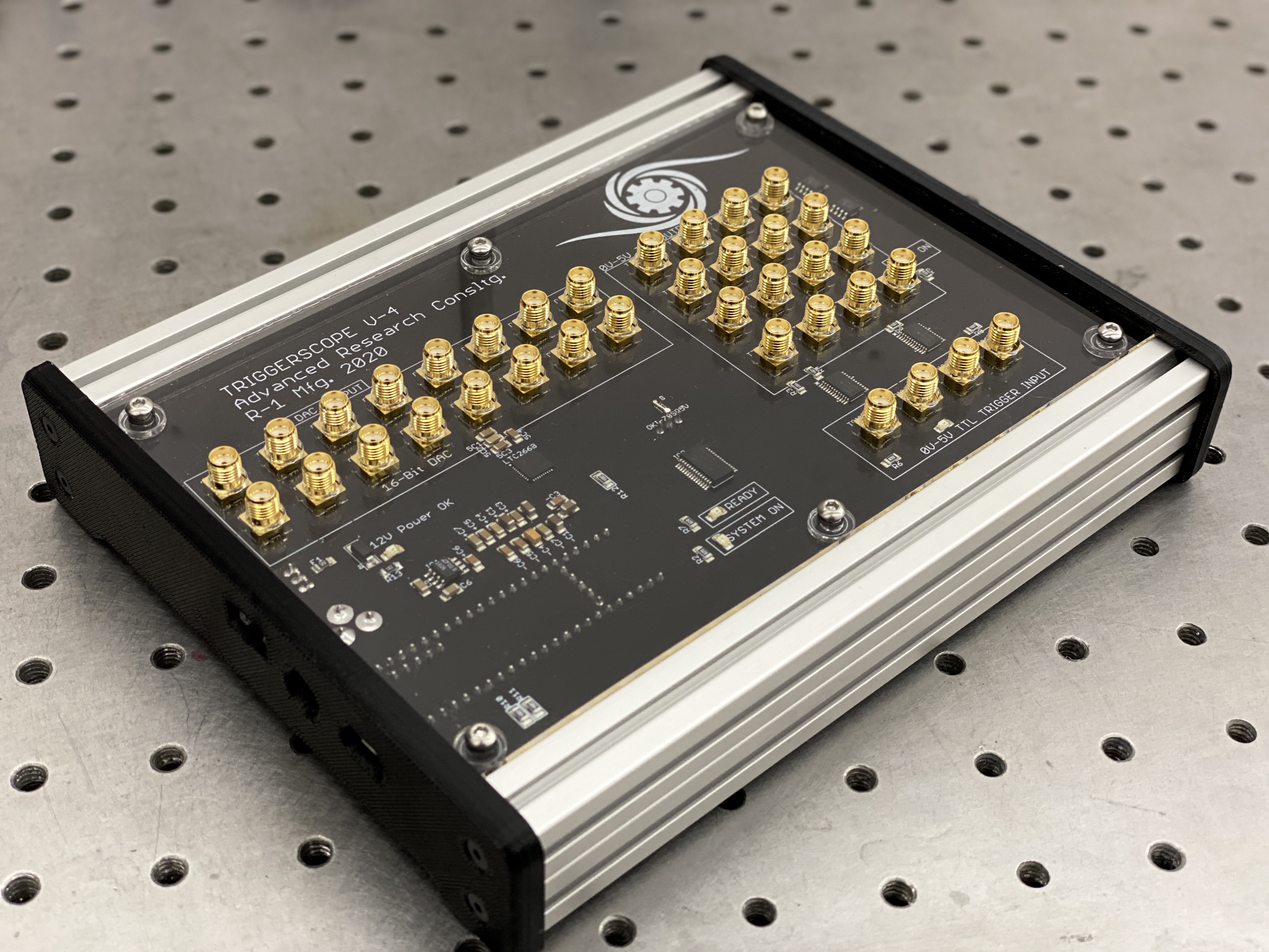
Triggerscope 4 Released – with New Software and New Micromanager Driver Options
I’m excited today to announce the release of the Triggerscope version 4. TG4 marks a major improvement in the performance and capability of the Triggerscope. New Features New Software In addition to the release of Triggerscope 4, ARC is introducing a python-based, multi-platform compatible standalone control application. Our application can be installed on Windows, OS-X, or […]
-
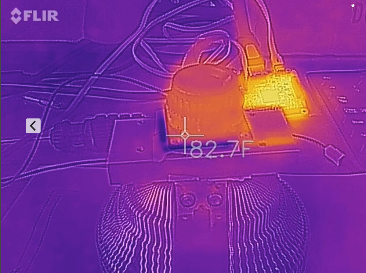
Raspberry Pi High Quality Camera – Can it be Cooled?
Thanks to some generous industry friends, I finally managed to get my hands on a seemingly unobtanium RPI “High Quality” camera. I’ll have more info on the camera itself regarding performance, but my first question was – “can it be effectively cooled? ” Fortunately, having run similar experiments on a Point Grey / FLIR camera, […]